
Open Tools, Interfaces, and Metrics for Implementation Security Testing
https://optimist-ose.org/
With contributions from
- Aydin Aysu (North Carolina State University)
- Gaetan Cassiers (Université catholique de Louvain)
- Daniel Dinu (Intel)
- Anuj Dubey (AWS Amazon)
- Fatemeh Ganji (Worcester Polytechnic Institute)
- Benoît Gérard (Agence nationale de la sécurité des systèmes d’information–ANSSI)
- Thomas Hiscock (Laboratoire d’électronique des technologies de l’information–CEA-Leti)
- Jens-Peter Kaps (George Mason University)
- Dev Mehta (Worcester Polytechnic Institute)
- Daniel Page (University of Bristol)
- Markku-Juhani Saarinen (Tampere University)
- Patrick Schaumont (Worcester Polytechnic Institute)
- Mirjana Stojilović (École Polytechnique Fédérale de Lausanne–EPFL)
- Emanuele Strieder (Fraunhofer Institute for Applied and Integrated Security AISEC)
- Jean-Pierre Thibault (NewAE Technology Inc.)
- Caner Tol (Worcester Polytechnic Institute)
- Marc Witteman (Keysight Technologies, Inc.)
WORKING DOCUMENT
CAPTURE INTERFACE FOR SIDE-CHANNEL AND FAULT INJECTION SETUPS
This document provides information about existing capture interfaces to suggest evaluation
criteria and recommended features useful for implementation security testing.
Glossary
This section enumerates and defines common terms related to capturing side-channel leakage. This list encompasses (virtually) the same definitions as in the OPTIMIST’s document describing “File Format for Traces” [1].
Channel: The source of a measurement of a physical value over time.
Trigger: A signal used to synchronize measurements with specific operations in the Target.
Target: The object of side-channel leakage measurements.
Noise (Algorithmic vs. Environmental): Unwanted variations in measurements that can obscure the desired signal in a trace.
- Algorithmic noise: Variations in the measured signal caused by the internal computations or processes of the device itself. This includes inherent randomness or variations due to the algorithm’s design, state transitions, or other non-target data dependencies.
- Environmental noise: External factors that introduce variability in the measurements unrelated to the device’s internal computations. This includes interference from the measurement setup, power supply noise, electromagnetic interference, or changes in the surrounding environment, such as temperature drift.
Sample: A single measurement of a Channel corrupted by Noise.
Trace: Vector corresponding to a sequence of measurements over time of a Channel during the Execution of the code on Target’s platform.
Metadata: Metadata is used to provide context and supplementary information about trace sets, such as the type of device being analyzed, the cryptographic algorithm being executed, the version of the algorithm implementation, the sampling rate and resolution of the measurement equipment, the environmental conditions during data collection, the applied countermeasures, and the date and time of data acquisition.
Environment: Things that affect the measurement, such as the location of the target, an x/y-stage that moves the target under an EM probe (or vice versa), temperature, emissions from nearby equipment, Faraday cages, etc. The Environment is constant during the measurement of a trace as it is monitored and controlled by the user. Ideally, it should be kept constant for the duration of the entire experiment, which sometimes can span over a long period of time.
Components in Typical Side-channel and Fault Analysis Setups
A typical side-channel and fault analysis setup consists of multiple components. The components are:
Workstation: The computer that is physically connected to the other components of the side-channel analysis setup. This computer orchestrates the acquisition of data and programs the target device, provides test vectors for the target device, and obtains the measurements.
Control: Controls the Target’s operation. In addition, it receives the test vectors from the Workstation and provides them to the target using an appropriate interface and protocol and receives responses from the target and provides them to the Workstation.
Target: The object of the side-channel leakage measurements.
Sensor: Senses a particular side channel, e.g., an EM prober, power probe, Electron Microscope, etc. The sensor is subject to Noise.
Signal Conditioning: Any device that improves the signal from the sensor before the Sampler measures it. E.g., filter, amplifier, or any analog pre-processing.
Sampler: Performs analog measurements. In many cases, this is an oscilloscope, but it can also be as simple as an analog to digital converter or as complex as a Software Defined Radio (SDR) or a spectrum analyzer. Features of a sampler include (but are not limited to) bandwidth, sampling rate, resolution, and memory size.
Communication: The hardware/software component offers means to connect components.
Trigger: A signal used to synchronize measurements of the Sampler with specific operations in the Target.
Power supply: Provides power to the Target.
Clock: Provides a clock signal to the Target. In some cases, this can also be reversed, where the clock from the target is sampled and used to align the Sampler.
Fault Generator: Generates a fault in the Target. This can be clock glitching, power glitching, EM fault injection, laser fault injection, etc.
Interface: The communication means between two components to exchange data for a specific purpose. These means can be physical or logical. Each interface can host multiple channels.
In addition to these main components, a set of auxiliary devices can be identified in a side-channel and fault analysis setup as follows.
- Signal generator for generating the clock
- A debugger that can be a function and a part of a component
- An input device gives inputs like glitches, plaintext, etc.
Usual Interfaces in Practice
This section enumerates the interfaces that exist in typical side-channel and fault analysis setups.
-
User Computer ↔️ Workstation
a. Purpose: the User Computer provides a human interface to the measurement setup, including control of the workstation, and visualization and analysis of measurement data.
b. Data: session control, configuration of workstation, transfer of formatted payloads (target firmware, target bitstream, target test vectors, measured data).
c. Features: bandwidth, latency, real-time response.
d. Logical layer: API for Session Control, API for Payload Formatting.
e. Physical layer: digital Data Transfer.
f. Example: USB, Ethernet. -
Workstation ↔️ Control Board
a. Purpose: allows sending/receiving information (e.g., configuration, state, plaintexts, ciphertexts, number of repetitions) to the Target, executing one or multiple operations with/without repeatedly sending all the inputs from the Workstation to the Target each time. In some setups, the Control Board may not be present as the Workstation is directly connected to the Target. In some instances, the communication of inputs and/or outputs can be handled for efficiency reasons by the Communication (see Interface 14) instead of the Control Board. In other cases, the Control Board can be merged with the Target.
b. Data: test vectors (e.g., inputs, expected outputs) and commands (e.g., execute a specific operation) from the Workstation to the Control Board, which are forwarded, as they are or in a different form, to the Target. The control board responds to the commands from the workstation, which may include status and outputs received by the control board from the target.
c. Features: bandwidth, latency, signaling, and communication protocols.
d. Logical layer: usually a user-defined API/protocol for control/data formatting.
e. Physical layer: digital data transfer.
f. Example: USB, UART, Ethernet. -
Workstation ↔️ Target (if directly connected)
a. Purpose: configuring the target prior to measurements, controlling the operation of the target before and during measurements, resetting/restarting the target (if unresponsive), and receiving data from the target (if applicable).
b. Data: configuration of the target (e.g., FPGA configuration file if the target is to be programmed), inputs (e.g., plaintexts on which the target cryptographic algorithm operates), operation mode (in case the target supports several operation or configuration modes, e.g., number of encryptions, frequency, enabling target operation (e.g., enabling the clock).
c. Features: bandwidth, voltage levels, signaling, and communication protocol.
d. Logical layer: file formats and corresponding drivers for communication protocols with the targets.
e. Physical layer: digital data transfer.
f. Example: USB, UART, Ethernet, PCIe. -
Sensor
 Signal conditioner
a. Purpose: transport of measured analog data to an analog conditioner, improving the signal.
b. Data: analog signal.
c. Features: impedance characteristics, bandwidth
d. Logical layer: NA
e. Physical layer: analog data transfer.
f. Example: cable connections (BNC, SMA…). -
Signal conditioner
Sampler
a. Purpose: ADC, Analysis
b. Data: analog signal captured from the sensor
c. Features: Filtering, DC block
d. Logical layer: NA
e. Physical layer: electrical connection.
f. Example: BNC, SMA, etc. -
Signal conditioner
Trigger
a. Purpose: synchronization between target and sampler.
b. Data: soft trigger signal, e.g., generated by analysis of signal vs. explicit generation by target.
c. Features: filtering and amplifying.
d. Logical layer: none.
e. Physical layer: electrical connection carrying digital signal (positive edge = start trigger, negative edge = end trigger)
f. Example: the signal conditioning module of an oscilloscope being connected to the power line of the target. -
Trigger ↔️ Target (unidirectional, can be Trigger
Target or Target Trigger)a. Purpose: timing synchronization between target and controller/sampler ensures alignment of traces.
b. Data: timing information signals the start of an execution.
c. Features: timing accuracy, jitter, rise time.
d. Logical layer: repeated events with accurate timing.
e. Physical layer: voltage edge over a single wire (typ. 3.3V or 5V).
f. Example: an oscilloscope’s waveform generator. -
Trigger
Sampler
a. Purpose: analysis, configuration.
b. Data: signals from trigger to sampler.
c. Features: bandwidth, speed, communication protocol, and its means.
d. Logical layer: API for handling control, configuration, synchronization, and error handling.
e. Physical layer: electrical connection.
f. Example: ethernet, serial, USB. -
Control
Trigger
a. Purpose: analysis, configuration.
b. Data: signals from trigger to sampler.
c. Features: bandwidth, speed, communication protocol, and its means.
d. Logical layer: API that is responsible for managing the communication, synchronization, and control between the control and trigger components.
e. Physical layer: electrical connection.
f. Example: ethernet, serial, USB. -
Power supply
Target
a. Purpose: powering on/off the target, force restart.
b. Data: none.
c. Features: low-noise, voltage levels.
d. Logical layer: none.
e. Physical layer: electrical connection.
f. Example: USB. -
Target
Sensor
a. Purpose: It ensures that the sensor captures relevant signals that can be analyzed to extract sensitive information (e.g., cryptographic keys) or study vulnerabilities in the target device’s operation.
b. Data: outputs of the target operation.
c. Features: sampling rate, trigger conditions, and other acquisition parameters to fine-tune the data capture.
d. Logical layer: API with commands that allow for configuring the sensor (sampling rate, trigger conditions), initiating and stopping captures, and handling the data after capture.
e. Physical layer: interface with the target device, including the physical connections, such as cables and pins.
f. Example: an oscilloscope probe attached to power or signal lines. -
Target ↔️ Communication
a. Purpose: target control; obtain and/or verify target result.
b. Data: inputs and outputs of the target operation (e.g., key, plaintext, ciphertext…)
c. Features: allow for different sizes
d. Logical layer: some protocol is needed (e.g., CW simple serial)
e. Physical layer: electrical connection
f. Example: UART, ethernet -
Control Board
Target
a. Purpose: Controlling the target.
b. Data: Control signal.
c. Features: timing, bit-width.
d. Logical layer: direct connections.
e. Physical layer: signal wires.
f. Example: wires. -
Communication ↔️ Workstation
a. Purpose: target control and data transfer. The communication module can be part of the components connected to one another, e.g., the control board can have an embedded communication module.
b. Data: all necessary packets required for trigger, control/ data packets.
c. Features: speed, bandwidth, throughput
d. Logical layer: packets format
e. Physical layer: USB
f. Example: USB, UART, ethernet -
Workstation
Fault generator
a. Purpose: configure the fault generator.
b. Data: characteristics of the fault (e.g., for a clock glitch: offset, period, etc.); perhaps enable (or arm) and/or disable (or disarm) signal
c. Features: resolution, bandwidth, speed, communication protocol, and its means.
d. Logical layer: API that abstracts communication protocol.
e. Physical layer: electrical connection.
f. Example: ethernet, serial, USB -
Workstation ↔️ Sampler
a. Purpose: analysis, configuration.
b. Data: configuration information going to the sampler, traces coming from the workstation.
c. Features: resolution, bandwidth, speed, communication protocol, and its means.
d. Logical layer: data formatted according to the API.
e. Physical layer: digital data transfer.
f. Example: ethernet, serial, USB. -
Workstation
Clock
a. Purpose: configure the clock signal to be supplied by the Clock to the Target and Fault Generator.
b. Data: configuration information (e.g., frequency, amplitude, width, duty cycle, rise time, fall time) from the Workstation to the Clock, which generates the clock signal used by the Target and Fault Generator.
c. Features: bandwidth, latency, characteristics of the communication protocol/API supported by the Clock.
d. Logical layer: data formatted according to the API of the clock generator
e. Physical layer: digital data transfer.
f. Example: USB, Ethernet. -
Clock ↔️ Target
a. Purpose: provide a reference clock to the target () or get the target clock to synchronize other components ( ).
).
b. Data: analog clock signal.
c. Features: impedance characteristics, voltage levels, frequency.
d. Logical layer: None.
e. Physical layer: analog Data Transfer.
f. Example: quartz on a board (), function generator connected to the target clock input (), internal clock exposed on a GPIO (). -
Clock
Sampler
a. Purpose: synchronizing the sampler with the target.
b. Data: clock signal(s) directly or indirectly clock-related information such as frequency or phase.
c. Features: frequency, voltage levels, phase with respect to a reference.
d. Logical layer: API for clock-specific information (frequency, phase) or none.
e. Physical layer: digital signal or digital data transfer.
f. Example: high bandwidth interfaces (SMA, BNC) or digital communication interfaces (UART, USB).
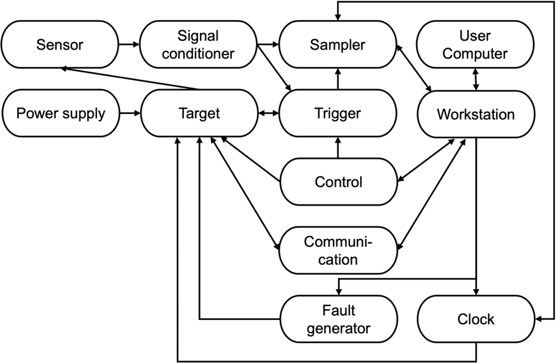
Figure 1: Interfaces in a side-channel/fault analysis setup.
Evaluation Criteria for APIs
The design and use of APIs aim to ease experiments and increase their quality. Some of the most important criteria for evaluating an API are:
Reproducibility: One of the main features of a scientific experiment which means that the experiment can be reproduced in conditions as close as possible to the original ones. For that, all relevant settings of the equipment in a setup used for an experiment should be saved together with the experimental data.
Portability: APIs may ease portability (genericity) from one equipment to another by standardizing the way we configure them. Such quality is helpful in obtaining standard-setting descriptions and is tightly linked to reproducibility when it comes to reproducing an experiment with different equipment.
Flexibility: An API potentially induces some restrictions due to some design choices. API flexibility is the quality of an API to be used in various (potentially very specific) scenarios. In the case of side-channel, such specific scenarios include:
- Multiple channel/equipment acquisition.
- Specific triggering.
- Specific capture modes such as sequence mode or continuous capture.
An API should be well-documented and easy to understand, use, and modify. In the worst case, the API must at least be thought to be easy/fast to fix/adjust when needed by an unusual experiment.
Efficiency: In an API, some design choices may have huge impact on performances. For side-channel, examples of bottlenecks are (depending on the type of experiment) measurement downloading, probe/target moving or equipment configuration. Thus, a special attention must be granted when designing an API to allow efficient implementations of the API. This can be quantified, for example, by the average number of traces measured by the entire setup or the number of test vectors processed by the Target per unit of time. Although ideally, one would aim to achieve all the above goals, sometimes that may not be possible because of the context, various limitations imposed by the Target, or available equipment. In that case, some characteristics of the API may be favored (e.g., efficiency) against others (e.g., portability).
Some other features of an API to be considered are as follows.
- Being standardized
- Impact of setups, e.g., voltage supply, probes, etc.
- Noise measurement
- Multi-channel ability, especially triggers & data.
- Options for setting up triggers.
- Continuous capture requires an event (basically, interrupt)- driven interface and a double buffer/ring buffer read-out ability (Picoscope drivers / C APIs support this)
Examples of Interfaces
The interfaces mentioned above have been employed in commercial and open-source setups. Here, we include the interfaces in two setups, namely FOBOS [2] and ChipWhisperer [3].
A. FOBOS
Based on the documentation from the FOBOS website, here is the extracted information (a–e) for each API [2]:
1. Target Communication Module
a. Data: the target Communication Module handles the data transfer between the target (Device Under Test) and the control system, including managing communication protocols.
b. Features:
- Configures target interface and manages output length.
- Handles communication over various interfaces like UART, SPI, etc.
c. Purpose: its purpose is to provide a reliable means of communication between the target and the controlling system, facilitating data exchange for side-channel analysis.
d. Logical Layer: works by interfacing with the control system to transmit and receive data from the target, ensuring proper synchronization and timing. According to FOBOS documentation, the 4-bit full-duplex FIFO interface is available.
e. Physical Layer: involves the physical connections (e.g., UART, SPI) between the target and the control system to facilitate data transfer.
2. Target Control Module
a. Data: the target Control Module manages control data related to the target, including triggering operations, resetting the target, and initiating other control signals for side-channel measurements.
b. Features:
- controls target clock settings, trigger operations, and resets.
- configures glitch and timeout behavior, as well as target selection for multi-target setups.
c. Purpose: its purpose is to ensure proper timing, control, and synchronization of the target during the side-channel analysis experiments.
d. Logical Layer: FIFO (bytewise), digital signal
e. Physical Layer: physically controls the target via hardware interfaces like GPIO, clock lines, and reset lines, all of which are connected to the target’s pins.
3. Open ADC Module
a. Data: the Open ADC Module handles the data acquisition from the target during side-channel measurements, acquiring analog signals like power traces.
b. Features:
- Provides ADC functionality for acquiring power traces.
- Requires the FOBOS Shield for proper operation.
c. Purpose: it aims to acquire high-fidelity analog traces from the target, typically for power analysis or glitch attacks.
d. Logical Layer: NA
e. Physical Layer: wire - Signals (traces)
4. Power Module
a. Data: the power module supplies power to the target, providing the necessary power for device operation during testing and side-channel measurements.
b. Features:
- supplies stable and configurable power to the target.
- integrates with the FOBOS Shield for power management.
c. Purpose: its purpose is to provide regulated power to the target, ensuring consistent performance during testing and experiments.
d. Logical Layer: NA
e. Physical Layer: wire, power
B. ChipWhisperer
The scope, target, capture, and analyzer APIs collectively enable comprehensive side-channel analysis using ChipWhisperer, covering hardware control, data acquisition, and data analysis [3]. The ChipWhisperer documentation describes each of these APIs. Here, we reformulate their definitions using the framework provided in this document.
1. Scope API
a. Data: the Scope API manages the capture and glitching functionalities of ChipWhisperer devices, handling data acquisition from the target.
b. Features: provides control over various scope settings, including sampling frequency, trigger conditions, and glitch parameters.
c. Purpose: facilitates the configuration and operation of the ChipWhisperer scope hardware to capture side-channel data and perform glitching attacks.
d. Logical Layer: offers an object-oriented interface in Python to configure and control the scope’s behavior, including methods for arming the scope and initiating captures.
e. Physical Layer: represents the physical ChipWhisperer scope hardware, such as the OpenADC Scope (Lite, Pro, Husky) and ChipWhisperer Nano Scope (Nano), which interface with the target to collect data.
2. Target API
a. Data: the Target API manages communication with the target, facilitating data exchange for side-channel analysis.
b. Features: supports various target types, including Simple Serial Targets and FPGA-based targets like CW305 and CW310, enabling flexible interactions with different DUTs.
c. Purpose: provides an interface to configure and control the target device, essential for setting up experiments and collecting relevant data.
d. Logical Layer: offers classes and functions to define target behavior, such as communication protocols and response handling, within the ChipWhisperer framework.
e. Physical Layer: encompasses the actual hardware targets, like the CW305 FPGA Target and CW310, which are connected to the ChipWhisperer scope for data acquisition.
3. Capture API
a. Data: the capture API handles the acquisition and storage of side-channel data during experiments, managing trace collection and storage.
b. Features: provides functionalities to start, stop, and manage data captures, including handling triggers and synchronization with the scope.
c. Purpose: ensures reliable and synchronized data collection from the target, crucial for accurate side-channel analysis.
d. Logical Layer: power trace and signals
e. Physical Layer: wires - SMA and 20-pin connectors.
4. Analyzer API
a. Data: the Analyzer API processes and analyzes the captured side-channel data, extracting meaningful information for cryptographic analysis.
b. Features: includes tools for data visualization, statistical analysis, and correlation techniques to interpret and capture results.
c. Purpose: aids in examining and interpreting side-channel data, facilitating the extraction of cryptographic keys or other sensitive information.
d. Logical Layer: NA
e. Physical Layer: NA
Open-source Capture Interface
Table 1 lists some of the open-source frameworks. As can be seen, a few frameworks offer publicly available capture interfaces. The lack of such interfaces not only affects the reproducibility of the results in SCA but also negatively impacts certification laboratories and standardization bodies that assess attack costs corresponding to side-channel and fault analysis.
Table 1: APIs in exemplary frameworks
| Framework | APIs | Links |
|---|---|---|
| Phobos | Target, capture | [Link] |
| ChipWhisperer | File handling, scope, target, capture, analyzer | [Link] |
| SCAPEgoat | File handling, scope, target, capture, analyzer | [Link] |
| SCALib | Analyzer | [Link] |
| SCARR | File handling, analyzer | [Link] |
| SCARED | File handling, analyzer | [Link] |
| LASCAR | File handling, analyzer, capture | [Link] |
| Sedpack/SCAAML | File handling, analyzer | [Link] |
| secbench | File handling, analyzer, capture, fault injection | [Link] |